Advantages of OFDM
Orthogonal frequency division multiplexing is commonly implemented in many emerging communications protocols because it provides several advantages over the traditional FDM approach to communications channels. More specifically, OFDM systems allow for greater spectral efficiency reduced intersymbol interference (ISI), and resilience to multi-path distortion.
Spectral Efficiency
In a traditional FDM system, each channel is spaced by about 25% of the channel width. This is done to ensure that adjacent channels do not interfere. This is illustrated in the diagram below, which shows the guard bands between individual channels.

Because of the requirement for guard bands, it is required to the symbol rate to allow for guard bands to exist. In general, the allowed channel bandwidth (Bw) is 2/Rs. As a result of this, the channels are able to be separated adequately.
n an OFDM system, on the other hand, the channels actually overlap. As a result, it is possible to maximize the symbol rate, and thus the throughput, for a given bandwidth. In the image below, we illustrate overlapping sub-carriers in an OFDM system. In this scenario, the channel bandwidth (Bw) approaches 1 / Rs. Thus, as the number of sub-carriers approaches infinity, OFDM systems allow for nearly double the spectral efficiency.
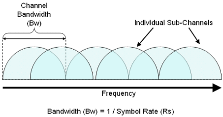
Note that with an OFDM system, it is still required to have a guard band between each individual channel. However, the effective symbol rate for the combined sub-carriers is greater than if a single carrier were used instead.

Note that the effect of using overlapping orthogonal sub-carriers also requires the use of a cyclic prefix to prevent intersymbol interference (ISI). Thus, some of the advantages gained through overlapping sub-carriers are compromised. However, the spectral efficiency advantage is great enough such that greater throughput is available in an OFDM system.
Reduced Inter Symbol Interference (ISI)
n mono-carrier systems, intersymbol interference is often caused through the multi-path characteristics of a wireless communications channel. Note that when transmitting an electromagnetic wave over a long distance, the signal passes through a variety of physical mediums. As a result, the actual received signal contains the direct path signal overlaid with signal reflections of smaller amplitudes. The diagram below illustrates how, at high symbol rates, reflected signals can interfere with subsequent symbols.
In wireless systems, this creates difficulty because the received signal can be slightly distorted. In this scenario, the direct path signal arrives as expected, but slightly attenuated reflections arrive later in time. These reflections create a challenge because they interfere with subsequent symbols transmitted along the direct path. These signal reflections are typically mitigated through a pulse-shaping filter, which attenuates both the starting and ending sections of the symbol period. However, as the figure above illustrates, this problem becomes much more significant at high symbol rates. Because the reflections make up a significant percentage of the symbol period, ISI will also be substantial.

OFDM systems mitigate this problem by utilizing a comparatively long symbol period. In addition, they do this without sacrificing throughput by utilizing multiple sub-carriers per channel. Below, we illustrate the time domain of OFDM symbols. Note that in an OFDM system, the symbol rate can be reduced while still achieving similar or even higher throughput.

Note from the illustration above that the time required for the reflections to fully attenuate is the same as before. However, by utilizing a smaller symbol rate, the signal reflections make up only a small percentage of the total symbol period. Thus, it is possible to simply add a guard interval to remove interference from reflections without significantly decreasing system throughput.
Other Advantages
- Flexibility of deployment across various frequency bands with little needed modification to the air interface.
- Averaging interferences from neighboring cells, by using different basic carrier permutations between users in different cells.
- Interferences within the cell are averaged by using allocation with cyclic permutations.
- Enables orthogonality in the uplink by synchronizing users in time and frequency.
- Enables Single Frequency Network coverage, where coverage problem exists and gives excellent coverage.
- Enables adaptive carrier allocation in multiplication of 23 carriers = nX23 carriers up to 1587 carriers (all data carriers).
- Offers Frequency diversity by spreading the carriers all over the used spectrum.
- Offers Time diversity by optional interleaving of carrier groups in time.
- Using the cell capacity to the utmost by adaptively using the highest modulation a user can use, this is allowed by the gain added when less carriers are allocated (up to 18dB gain for 23 carrier allocation instead of 1587 carriers), therefore gaining in overall cell capacity.
Disadvantages of OFDM
- Peak to average power ratio (PAPR) is high
- High power transmitter ampli ers need linearlization
- Low noise receiver ampli ers need large dynamic range
- Capacity and power loss due to guard interval
- Bandwidth and power loss due to the guard interval can be signi cant
- The guard interval consumes 20% of the bandidth and transmit power in IEEE802.11a
- Frequency off sets and phase noise sensitivity
- Phase noise is especially acute at high carrier frequencies
- The OFDM signal has a noise like amplitude with a very large dynamic range, therefore it requires RF power amplifiers with a high peak to average power ratio.
- It is more sensitive to carrier frequency offset and drift than single carrier systems are due to leakage of the DFT.
